Ternary multiplexer (selector)
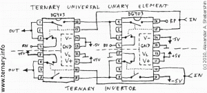
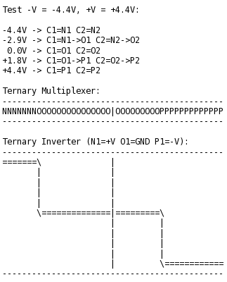
My hardware design described earlier has been proven to be working:
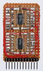
Today two DG403s, four chip-capacitors 0.022 uF and 15-pin header were composed by me to the dual ternary multiplexer TRI41D:
TRI41D pins description:
 1.  S - select command (choose pins to connect)
 2. N1 - connected to C1 if S="N" (negative)
 3. O1 - connected to C1 if S="O" (ground)
 4. P1 - connected to C1 if S="P" (positive)
 5. C1 - connected to N1,O1,P1 based on voltage level on S
 6. N2 - connected to C2 if S="N" (negative)
 7. O2 - connected to C2 if S="O" (ground)
 8. P2 - connected to C2 if S="P" (positive)
 9. C2 - connected to N2,O2,P2 based on voltage level on S
10.-V - negative power
11.GND - ground
12.+V - positive power
P.S. Recently I designed PCB of double ternary multiplexer TRIMUX – see www.trimux.com


 I'm software developer (mostly C/C++) who relocated from Russia to United States in 2004. Lived in NY, CO and now CA. Since 1998 my Internet nickname is "Shaos" (not chaos)...